


Manufacturing dictionary
AQL (Acceptable Quality Level)
A statistical sampling technique used to determine the acceptable level of defects or non-conformities in a batch or lot of manufactured components.
Backlash
The amount of clearance or play between mating gear teeth or pulley teeth. It is necessary to accommodate manufacturing tolerances and ensure smooth operation but should be minimized for precise motion control.
Belt Drive
A power transmission system that uses a belt, typically made of rubber or other flexible material, to transfer rotational motion between two pulleys.
Belt Tension
The force applied to a timing belt to ensure proper engagement with the pulleys. Correct tension is crucial for maintaining accurate motion and preventing slippage.
Belt Length
The total length of a timing belt, usually expressed in millimeters or inches. It determines the required center distance between pulleys and affects the speed ratio of the drive system.
Belt Profile
The shape and dimensions of the teeth on a timing belt, such as HTD (High Torque Drive), GT (Gates Tooth), or PowerGrip GT3. Different profiles offer specific performance characteristics and compatibility with corresponding pulleys.
Belt Width
The width of a timing belt, measured from one edge to the other. It should match the pulley's width to ensure proper engagement and power transmission.
Broaching
A machining process that uses a specialized tool called a broach to remove material in a precise and controlled manner, typically used to create keyways, splines, or other complex profiles.
CAD
Computer-Aided Design, also known simply as CAD, is a type of software that helps the engineer in the design process of a particular machine or even single components. Files created using such software are also called CAD files.
CAM
Computer-Aided Manufacturing (CAM) is a technology that enables engineers to program the method of manufacturing based on the CAD file. CAM software utilizes both computer software and hardware to automate and control the manufacturing process. It involves the use of computer systems to generate, optimize, and control the instructions needed to manufacture a product.
Coupling
A device used to connect two shafts together, transmitting torque while accommodating misalignment, vibration, or shock.
Chain Drive
A power transmission system that uses a roller chain to transmit rotational motion between sprockets.
Chain Pitch
The distance between adjacent chain pins or rollers. It is an important parameter for chain drive systems and determines the size and compatibility of sprockets.
Chain Length
The total length of a chain loop, measured from one end to the other. It is crucial for determining the required center distance between sprockets and ensuring proper tensioning.
CMM Inspection
A Coordinate Measuring Machine (CMM) is a precise measuring device that uses probes and sensors to accurately measure the dimensions and geometry of components.
D-Bore
A type of bore or hole in a component that is shaped like the letter "D," offering a precise and secure fit with a corresponding shaft.
First Article Inspection
The process of thoroughly inspecting and verifying the dimensions, tolerances, and performance of the first manufactured piece to ensure it meets the required specifications before proceeding with mass production.
Friction Loss
The energy lost due to friction between moving components in a synchronous drive system. Minimizing friction loss helps optimize efficiency and reduce wear.
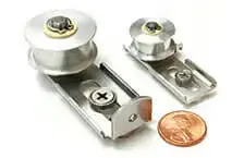
Friction Wheel
A wheel that utilizes friction between its surface and a belt or other contacting component to transmit motion.
Gear
A mechanical component with toothed cogs that is used to transmit rotational motion and torque. The teeth of the gear mesh with the teeth of another gear or a toothed surface, such as a pulley or a sprocket to transmit power and motion from one shaft to another. As the teeth of two gears interlock, they create a positive engagement, allowing smooth and efficient power transmission. Gears come in various types, including spur gears, helical gears, bevel gears, or worm gears.
- Spur gears are the most common type and have straight teeth that are parallel to the gear axis. They provide simple and efficient power transmission but can produce noise and vibration due to their teeth engaging all at once.
- Helical gears have angled teeth that are spiral-shaped, allowing for smoother engagement and quieter operation compared to spur gears. They can handle higher loads but may introduce axial thrust forces.
- Bevel gears are used to transmit motion between intersecting shafts at an angle. They have conical-shaped teeth and are commonly found in applications such as automobile differentials and power tools.
- Worm gears consist of threaded screw-like gear (worm) that meshes with a toothed wheel (worm wheel). They provide high gear reduction ratios and are often used when high torque and low-speed motion are required.
Hobbing
Hobbing is the process of using a hobbing machine and a cutting tool to cut teeth, groves, or splines into a material. This process is used for producing spur and helical gears, as well as other parts such as ratchets, sprockets, and splines.
Honing
A precision machining process that uses abrasive stones or tools to remove small amounts of material and achieve a smooth and precise surface finish on a bore or cylindrical component.
Lubrication
The application of a lubricant, such as oil or grease, to reduce friction, wear, and heat generation between moving components in synchronous drive systems.
Load Capacity
The maximum amount of force or load that a component, such as a gear or pulley, can withstand without failure. It is an important consideration for ensuring system reliability and longevity.
Mounting Options
Various methods and configurations for securely attaching components, such as pulleys or gears, to shafts, motors, or frames. Common mounting options include set screws, keyways, clamping mechanisms, and shaft couplings.
Misalignment
The deviation or offset between the rotational axes of two components, such as pulleys or gears. Misalignment can lead to decreased performance, increased wear, and premature failure.
Keyway
A slot or groove machined into a shaft or hub to provide a positive mechanical connection, allowing torque transfer between the two components.
Optical Comparator
A device that uses optics and lighting to compare the shape and dimensions of a part to a master template, allowing for visual inspection and measurement of critical features.
Pitch
The distance between corresponding points on adjacent teeth of a gear or pulley. It is typically measured along the pitch circle and is an important parameter for proper synchronization.
Pitch Diameter
Also known as a pitch circle, is the diameter of the imaginary circle formed by the tops of the teeth on a pulley or gear.
Pitch Line
The theoretical line along which the belt or chain engages with the teeth of a pulley or gear.
Power Transmission
The process of transmitting mechanical power from a source (such as a motor) to a driven component (such as a pulley or gear) through the use of belts, chains, gears, or shafts.
Service Life
The expected duration of reliable operation for a component or system under specific operating conditions. It is influenced by factors such as load, speed, lubrication, and maintenance.
Shaping
Shaping is a process that uses a shaping machine to machine the teeth of a gear one by one, using a shaping tool. This process is slower and is often used for smaller gears and low-volume production, especially in the case of custom gears. Hobbing is significantly faster and commonly used in the higher-volume production of larger gears.
Shaft
A rotating cylindrical component used to transmit power or motion between different parts of a machine or system.
Sprocket
A toothed wheel with radial projections (teeth) that engage with the links of a chain, facilitating the transfer of rotary motion.
Splines
Longitudinal ridges or grooves on a shaft or gear that interlock with corresponding grooves or ridges on another component, allowing torque transfer while enabling slight axial movement.
Pulley flanges
Timing pulley flanges are components used in the production of timing pulleys. A pulley flange is a steel ring designed to fasten the side guide of the timing belt. It sits on either side of the teeth of the pulley and its purpose is to maintain the tight contact between the belt and timing pulley in a synchronous power transmission drive.
Pulley flanges help control the timing belt's alignment, as it drives onto the timing belt pulley. In order to stop the belt from slipping off the pulley, at least one flange must be on each side of the belt. Timing pulley flanges are manufactured to perfectly fit timing pulleys of the same pitch and size. The dimensions of a pitch are determined by the number of grooves. Flanges are very commonly used in synchronous drives with timing belt pulleys as they provide much better timing belt performance and reliability.
Prototype
A prototype is a sample or preliminary version of a motion component that is created during the prototyping stage of product development. It is a functional representation of the intended motion component, designed to test and validate its design, functionality, and performance before proceeding with full-scale production.A prototype motion component can be manufactured using various techniques, such as machining, 3D printing, or casting, depending on the material, complexity, and intended use.
The purpose of developing a prototype motion component is to identify and address any design flaws, manufacturing challenges, or performance issues early in the development process. Prototyping motion components helps ensure that the final product meets the desired specifications, performance requirements, and customer expectations.
Prototype Stage
The initial phase of product development is where a working model or prototype is created to test and validate the design, functionality, and performance before proceeding with full-scale production.
Reverse Engineering
The process of analyzing and dissecting a finished product to understand its design, construction, and functionality in order to recreate or improve upon it.
Timing pulley stock
Timing pulley stock is a bar of pulley stock material that is prepared for further cutting, shaping, and other potential machining processes. Machining a timing pulley from bar stock involves cutting teeth into the circumference of the stock to create the desired tooth profile. This process may be done using manual or CNC machinery, depending on the complexity of the pulley design and the precision required.
Pulley stock is usually used for producing custom timing pulleys that are not available in standard sizes or tooth profiles. It is also used in creating prototypes and replacement components. Using the bar pulley stock in machining the custom timing pulleys enables the designers and engineers the production of pulleys that meet their exact specifications, allowing for greater flexibility in the design and performance of power drive transmission systems.
Timing belts
Timing belts are fundamental components for all types of power drives. A timing belt is a type of flexible belt used in power drive systems to convey motion. Usually, they are made from rubber but some belts are made from polyurethane or neoprene. Timing belts are attached to at least two timing belt pulleys, often with the help of pulley flanges. This enables a successful and efficient power transfer in a synchronous drive and prevents the belt from slipping and mechanic damage.
Timing belts have teeth on their inner side, that can be locked with the grooves on a timing pulley or a sprocket. Pulley flanges are used to keep the belt securely attached to the timing pulley and guide its motion on it. Because of this, the belt moves at the same speed as the pulley, which results in consistent power transmission.
Timing belts usually do not require any lubrication and are considered a more cost-effective option compared to other types of motion parts. They can be also quite easily replaced in case of mechanical damage.
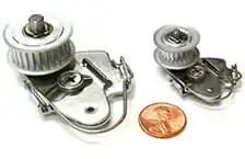
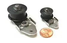
Timing belt tensioners
Timing belt tensioners are often important components in a timing belt-based power drive system that main purpose is to maintain the correct tension on the belt, ensuring the proper transmission of power. York Industries has been one of the first companies in the world to add timing belt tensioners to our product catalog.
A timing belt tensioner is typically a spring-loaded pulley that applies pressure to the timing belt to keep it tight in place. A correctly functioning timing belt tensioner is essential to smooth and efficient power transmission in a synchronous power drive. If the tensioner fails, the timing belt may become loose, which can cause damage to both the belt and the power drive engine. It is advised to have the timing belt tensioner checked regularly and either adjusted or replaced as needed.
For engineers and designers, tensioners can be a game-changer when designing efficient and effective synchronous drives. By using tensioners, you can easily adjust the tension of a belt, which can help prevent slippage and ensure that the belt stays in place, even under heavy loads. This is especially important for drive systems that require a lot of power.
One of the benefits of using a tensioner is that it allows you to use stock belts, rather than having to order custom belts. This can save time and money, as custom belts can be expensive and take longer to produce. Tensioners also enable adjustment for any drive variations, which makes installation and servicing of the whole drive system much more manageable.
Timing belt pulley
Timing belt pulleys are motion parts that form a drive system together with a timing belt or shafts. The pulleys are used for proper timing and synchronization of the system, making sure that the power transmission is working efficiently and with the exact timing and ratio that is desired.
Timing Pulleys are a type of pulley with visible teeth or pockets outside its diameter. Configured with a timing belt with the same pitch, these timing pulleys ensure the correct power transmission in a synchronous drive system. Pulley flanges are often used to guide the belt on the timing pulley and fasten it securely on it. Custom timing pulleys are made to order unique components that each have different product characteristics, depending on the customers’ needs.
Most timing pulley has grooves along the outside of their diameter, which serves the same purpose as sprockets, preventing the misalignment of the timing belt. Misalignment occurs when the belt slips off the track, disturbing the power drive transmission. The timing belt needs to be tightly secured to the grooves of the pulley. Sometimes, toothed belts, timing belt tensioners, and different kinds of idlers are also used depending on the type and purpose of the power drive. Correct positioning between the pulley's grooves and the timing belt is crucial for the right power transmission.
Tolerance
Tolerance is the amount of acceptable variation from the standard dimensions. Gear tolerance standards are set by the American Gear Manufacturers Association (AGMA) for gear manufacturing, ensuring the interchangeability and proper functionality of gears. York Industries is an official AGMA member and complies with the newest standards of the organization.
Torque
A measure of rotational force, typically expressed in Newton-meters (Nm), that describes the tendency of a force to rotate an object about an axis.
Torque Limiter
A device designed to protect a system from excessive torque by disengaging or slipping when the torque exceeds a specified limit, preventing damage to components.
Tooth Pitch
The distance from the center of one tooth to the center of the adjacent tooth on a timing belt. It determines the tooth size and affects the overall size and performance of the belt.
Tooth Profile
The shape and configuration of the teeth on a pulley or gear, are designed to mesh accurately with a corresponding belt or other mating component.
Torsional Rigidity
The resistance of a component or system to torsional deflection or twisting under an applied torque.