


Belt Pitch: Profile & Selection
A belt ‘profile’ refers to the shape of the belt tooth when viewed from the side, just like a ‘profile’ portrait of a person. This two dimensional view will show the belt in a flat position and not curved around a pulley. The shape of the teeth, including how they blend into the belt and the thickness of the belt itself, are all part of the profile. When individual teeth are attached to a belt, the distance from tooth to tooth is the ‘pitch’ of the belt. For example, a 2mm GT2 belt will have a tooth every 2 millimeters and each tooth has a GT2 profile.
When considering the price of different belt profiles, it's important to factor in the long-term benefits and durability of the material used.
The pulley that a belt mates with needs to have the same profile and pitch as the belt itself. Pulley profiles are generally mirror images (inverses) of the belt profile since they must mate together, and this is especially true for belts made from flexible rubber. But the pulley version of the profile will have small modifications to ease the plastic belt’s entry and exit into the metal grooves of the pulley.
There are two general types of belt profiles, trapezoidal and curvilinear. Older belt profiles were defined and approved by the Mechanical Power Transmission Association in the mid Twentieth Century and are still industry standards today. These are trapezoidal in shape and are heavily used in the power transmission industry since they are standards that have been in use for decades. The other types of profiles are curvilinear and these tend to be proprietary designs. Curvilinear profiles take advantage of advances in machine tools and computers to optimize the profiles beyond those of trapezoidal designs. Curvilinear profiles generally provide increased horsepower, decreased noise, and reduced tooth wear. Whatever belt profile and pitch is used, the pulley must also use the mating version of the same profile at the same pitch.
Choosing a profile for a synchronous drive design is not only determined by horsepower.
Modern belts with fiberglass, polyester and Kevlar cord can generally handle far more horsepower than the drive system requires. And they are strong enough that belt breakage is rarely seen but rather ‘cogging’ where a belt will hop over one or more teeth on one of the pulleys rather than engage. This is solved with either a wider belt of the same profile or a profile that can provide more horsepower for the same belt width. It can also be solved by changing the pitch since the greater the pitch, the larger the tooth and the more load each tooth can carry. For example, in moving from a 2 mm pitch to a 3 mm pitch, while the space between teeth increases only 50%, the load carrying capacity of each tooth can increase from 6 to 10 times since the cross sectional area and load bearing surface increases dramatically. The trade-off is that you need enough teeth in mesh with the pulleys to prevent cogging or skipping of the belt under load. So for equivalent loads, smaller pulley diameters require smaller pitches while larger pitches can be used if you have the available real estate in your design to handle larger diameter pulleys. The presence of cogging indicates that there is a problem with the drive system. The order to troubleshoot a cogging system would be:
-
Is the belt properly installed and tensioned?
-
Are the teeth in mesh adequate for the load?
-
Is there a large shock load present or is it a reversing drive? (these conditions are the most demanding on a drive system)
-
Finally, is the belt pitch and belt width adequate for the load on the system?
Selecting the right timing belt is crucial for ensuring the efficiency and longevity of your drive system.
The last three solutions require changes to the design while the first solution (proper tension and installation) is a training and installation issue.
So since belt horsepower capacity isn’t generally the limiting factor, the consideration is often what profiles are being used by the suppliers of available components or profiles that your company already has parts in inventory to support. For example, if you need a particularly long belt, you would want to try to find one that was a stock product to avoid a custom tooling charge and whatever profile that length was available in would then become the profile for your design. Or if you have special needs such as low noise or low tooth wear, you would look at curvilinear profiles rather than trapezoidal ones. The following charts show the rated torque for a number of belt profiles across various speed and horsepower settings for the same timing pulley diameters and belt widths. In this apples-to-apples comparison, you can see that there is generally a wide overlap among belt profiles in their ability to handle equivalent loads, especially at lower speeds and power.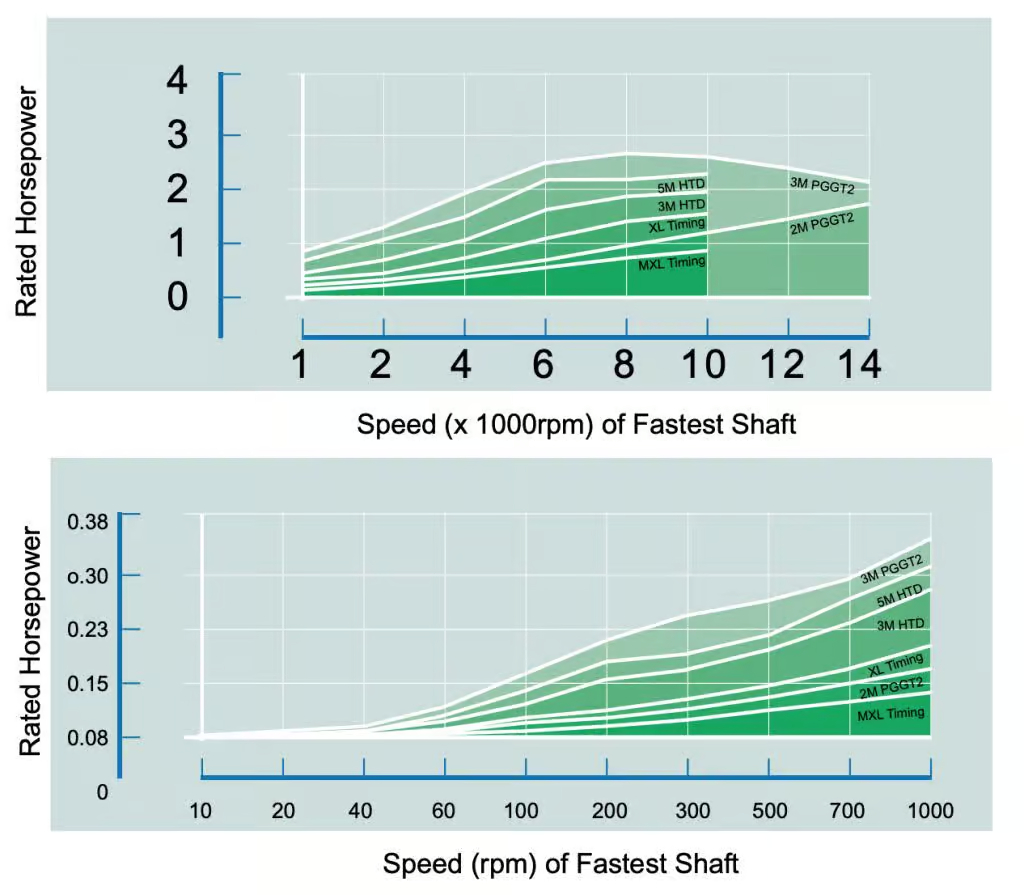
When you do choose a profile you can get specific engineering data for your particular application and belt profiles using a computer design tool such as York Industries’ free DriveWorks software. This tool provides data such as static tension on the belt, belt deflection, teeth in mesh, and percent of actual bad to design bad that the specific drive design you have chosen actually delivers. This is ideal for design files required by ISO-9001 or FDA requirements since the software prints out all the information in a format that documents the specific system parameters in a way that allows easy comparison between different profiles or designs and then serves as documentation for why the final design was chosen. It is also an excellent way to avoid grossly overdesigning the drive system, which is easy to do given the capabilities of today’s belts and the time and difficulty of manually calculating what DriveWorks can provide in seconds.
In summary, profile and pitch selection is a tradeoff between what component manufacturers offer on their products that you have to include in your design, parts that your company might already stock or have experience with, and the power transmission and space requirements of your design. The wide overlap in bad carrying capacity between profiles and pitches generally provides multiple pitch and profile options for the drive designer.