


Synchronous Drive Specifications
SCOPE
This standard applies to those belts and pulleys intended for mechanical power transmission, and where positive indexing or synchronous type service may be required. These specifications cover three standard belt sections, which are established on the basis of belt pitch. These sections are designated MXL (0.080 inch pitch), XL (0.200 inch pitch), and L (0.375 inch pitch). It also covers dimensions for two double-sided sections: DXL (0.200 inch pitch), and DL (0.375 inch pitch). Dimensions of synchronous belts and pulleys together with basic design data are covered in this standard. Dimensions in customary English units are provided. This standard does not apply to automotive drives for which other standards exist.
SYNCHRONOUS BELT PULLEYS
DIAMETERS
Table 1 lists the standard pulley diameters by belt section (pitch). Figure 1 defines the pitch, pitch diameter, outside diameter, and the pitch line differential.
WIDTHS
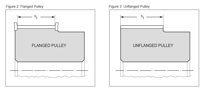
The standard pulley widths are shown in Table 2 for each belt section. The nominal pulley width is specified in terms of the maximum standard belt width the pulley will accommodate. For example, only one standard nominal width is specified for the XL Belt Section – 0.38 inches. This pulley width can be used for the standard XL belt widths of 0.25 and 0.38 inches. The actual minimum pulley width, whether flanged or unflanged, is also specified in Table 2 and shown in Figures 2 and 3.
SIZE DESIGNATION
Pulleys are designated by the number of grooves, the belt section, and a number representing 100 times the nominal width. For example, a 30 groove L section pulley with a nominal width of 0.75 inches would be designated by the number 30L075.
GROOVE PROFILE
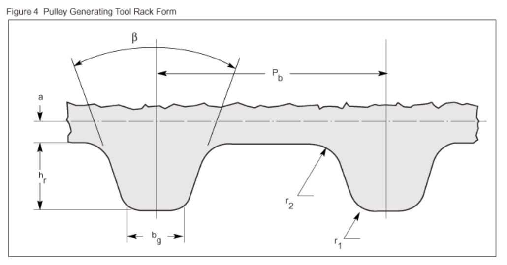
The groove profile is defined as the profile formed by the generating tool rack form described in Table 3 and Figure 4. The sides of the grooves shall be free of surface defects, and the edges of all grooves shall be rounded. The flanks of the grooves shall have a finish of 125 microinches, or better.
FLANGE DIMENSIONS
The details of suggested pulley flange design are shown in Table 4 and Figure 5.
KEYSEATS
Keyseats in the hubs of pulleys are shown in Figure 6 and shall conform to the dimensions and tolerances given in Table 5. BORE
TOLERANCES
Table 6 gives the bore tolerances for belt pulleys.
MISCELLANEOUS TOLERANCES
Table 7 includes the following miscellaneous pulley tolerances: Outside Diameter, Radial Runout, Axial Runout, Pitch Accuracy
| No. of Grooves |
BELT SELECTION | |||||
|---|---|---|---|---|---|---|
| MXL (0.080) Diameters |
XL (0.200) Diameters |
L (0.375) Diameters |
||||
| Pitch | Outside | Pitch | Outside | Pitch | Outside | |
| 10 | 0.255 | 0.235 | 0.637 | 0.617 | 1.194* | 1.164* |
| 12 | 0.306 | 0.286 | 0.764 | 0.744 | 1.432* | 1.402* |
| 14 | 0.357 | 0.337 | 0.891 | 0.871 | 1.671 | 1.641 |
| 16 | 0.407 | 0.387 | 1.019 | 0.999 | 1.910 | 1.880 |
| 18 | 0.458 | 0.438 | 1.146 | 1.126 | 2.149 | 2.119 |
| 20 | 0.509 | 0.489 | 1.273 | 1.253 | 2.387 | 2.357 |
| 22 | 0.560 | 0.540 | 1.401 | 1.381 | 2.626 | 2.596 |
| 24 | 0.611 | 0.591 | 1.528 | 1.508 | 2.865 | 2.835 |
| 26 | 0.662 | 0.642 | 3.104 | 3.074 | ||
| 28 | 0.713 | 0.693 | 1.783 | 1.763 | 3.342 | 3.312 |
| 30 | 0.764 | 0.744 | 1.910 | 1.890 | 3.581 | 3.551 |
| 32 | 0.815 | 0.795 | 2.037 | 2.017 | 3.820 | 3.790 |
| 34 | 0.866 | 0.846 | ||||
| 36 | 0.917 | 0.897 | 2.292 | 2.272 | 4.297 | 4.267 |
| 40 | 1.019 | 0.999 | 2.546 | 2.526 | 4.775 | 4.745 |
| 42 | 1.070 | 1.050 | 2.674 | 2.654 | ||
| 44 | 1.120 | 1.100 | 2.801 | 2.781 | 5.252 | 5.222 |
| 48 | 1.222 | 1.202 | 3.056 | 3.036 | 5.730 | 5.700 |
| 60 | 1.528 | 1.508 | 3.820 | 3.800 | 7.162 | 7.132 |
| 72 | 1.833 | 1.813 | 4.584 | 4.564 | 8.594 | 8.564 |
| 84 | 10.027 | 9.997 | ||||
* Usually not available in all widths - consult supplier
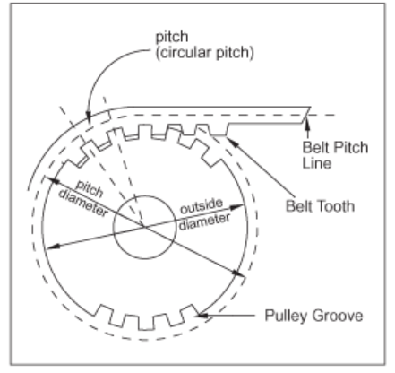
Figure 1 Pulley Dimensions
| BELT SELECTION | STANDARD NOMINAL PULLEY WIDTH | STANDARD PULLEY WIDTH DESIGNATION | MINIMUM PULLEY WIDTH | |
|---|---|---|---|---|
| FLANGED bf |
UNFLANGED bf |
|||
| MXL (0.080) | 0.25 | 025 | 0.28 | 0.35 |
| XL (0.200) | 0.38 | 037 | 0.41 | 0.48 |
| L (0.375) | 0.50 | 050 | 0.55 | 0.67 |
| 0.75 | 075 | 0.80 | 0.92 | |
| 1.00 | 100 | 1.05 | 1.17 | |
| BELT SELECTION | NUMBER OF GROOVES |
Pb ± 0.0001 |
β ± 0.25 (Degrees) |
hr +0.002 -0.000 |
bg +0.002 -0.000 |
r1 ± 0.001 |
r2 ± 0.001 |
2a |
|---|---|---|---|---|---|---|---|---|
| MXL | 10 thru 23 24 & over |
0.0800 | 56 40 |
0.025 | 0.024 0.265 |
0.012 | 0.009 | 0.020 |
| XL | 10 & over | 0.2000 | 50 | 0.055 | 0.050 | 0.024 | 0.024 | 0.020 |
| L | 10 & over | 0.3750 | 40 | 0.084 | 0.122 | 0.034 | 0.021 | 0.030 |
| BELT SELECTION | MINIMUM FLANGE THICKNESS | MINIMUM FLANGE HEIGHT* |
|---|---|---|
| *Flange outside diameter equals pulley outside diameter plus twice flange height. | ||
| MXL (0.080) | 0.023 | 0.020 |
| XL (0.200) | 0.029 | 0.040 |
| L (0.375) | 0.050 | 0.065 |
| SHAFT DIAMETER | WIDTH, wk* | DEPTH, wk* +0.015 -0.000 |
|---|---|---|
| *Tolerance on width, wk: For width up through 1/2 (0.500)......+0.002, -0.000 inches For width over 1/2 (0.500) up through 1 (1.000)..........+0.003, -0.000 inches For width over 1 (1.000).................+0.004, -0.000 inches |
||
| Up Through 7/16 (0.44) Over 7/16 (0.44) To and Incl 9/16 (0.56) Over 9/16 (0.56) To and Incl 7/8 (0.88) Over 7/8 (0.88) To and Incl 1-1/4 (1.25) |
3/32 (0.094) 1/8 (0.125) 3/16 (0.188) 1/4 (0.250) |
3/64 (0.047) 1/16 (0.062) 3/32 (0.094) 1/8 (0.125) |
| Over 1-1/4 (1.25) To and Incl 1-3/8 (1.38) Over 1-3/8 (1.38) To and Incl 1-3/4 (1.75) Over 1-3/4 (1.75) To and Incl 2-1/4 (2.25) Over 2-1/4 (2.25) To and Incl 2-3/4 (2.75) |
5/16 (0.312) 3/8 (0.375) 1/2 (0.500) 5/8 (0.625) |
5/32 (0.156) 3/16 (0.188) 1/4 (0.250) 5/16 (0.312) |
| Over 2-3/4 (2.75) To and Incl 3-1/4 (3.25) Over 3-1/4 (3.25) To and Incl 3-3/4 (3.75) Over 3-3/4 (3.75) To and Incl 4-1/2 (4.50) Over 4-1/2 (4.50) To and Incl 5-1/2 (5.50) |
3/4 (0.750) 7/8 (0.875) 1 (1.000) 1-1/4 (1.250) |
3/8 (0.375) 7/16 (0.438) 1/2 (0.500) 5/8 (0.625) |
| DIAMETER OF BORE | LENGTH OF BORE | |||||||||||
|---|---|---|---|---|---|---|---|---|---|---|---|---|
| Up Thru 0.75 | Over 0.75 To And Including 1.00 | Over 1.00 To And Including 1.25 | Over 1.25 To And Including 1.50 | Over 1.50 To And Including 2.00 | Over 2.00 To And Including 2.50 | Over 2.50 To And Including 3.00 | Over 3.00 To And Including 3.50 | Over 3.50 To And Including 4.00 | Over 4.00 To And Including 4.50 | Over 4.50 To And Including 5.50 | Over 5.50 To And Including 6.00 | |
| Up thru 0.50 | +0.0015 +0.0005 |
+0.0015 +0.0005 |
+0.0015 +0.0005 |
+0.0015 +0.0005 |
+0.0015 +0.0005 |
|||||||
| Over 0.50 To And Including 1.00 | +0.0015 +0.0005 |
+0.0015 +0.0005 |
+0.0015 +0.0005 |
+0.0015 +0.0005 |
+0.0020 +0.0005 |
+0.0020 +0.0005 |
+0.0020 +0.0005 |
|||||
| Over 1.00 To And Including 1.50 | +0.0015 +0.0005 |
+0.0015 +0.0005 |
+0.0015 +0.0005 |
+0.0020 +0.0010 |
+0.0020 +0.0010 |
+0.0020 +0.0010 |
+0.0020 +0.0010 |
+0.0000 +0.0010 |
||||
| Over 1.50 To And Including 2.00 | +0.0020 +0.0005 |
+0.0020 +0.0005 |
+0.0025 +0.0010 |
+0.0025 +0.0010 |
+0.0025 +0.0010 |
+0.0025 +0.0010 |
+0.0025 +0.0010 |
+0.0030 +0.0010 |
+0.0030 +0.0010 |
+0.0030 +0.0010 |
||
| Over 2.00 To And Including 2.50 | +0.0020 +0.0005 |
+0.0025 +0.0010 |
+0.0025 +0.0010 |
+0.0025 +0.0010 |
+0.0025 +0.0010 |
+0.0025 +0.0010 |
+0.0030 +0.0010 |
+0.0030 +0.0010 |
+0.0030 +0.0010 |
|||
| Over 2.50 To And Including 3.00 | +0.0025 +0.0010 |
+0.0025 +0.0010 |
+0.0025 +0.0010 |
+0.0025 +0.0010 |
+0.0030 +0.0010 |
+0.0030 +0.0010 |
+0.0035 +0.0015 |
|||||
| Over 3.00 To And Including 3.50 | +0.0030 +0.0010 |
+0.0030 +0.0010 |
+0.0030 +0.0010 |
+0.0030 +0.0010 |
+0.0035 +0.0010 |
+0.0035 +0.0010 |
+0.0040 +0.0015 |
|||||
| Over 3.50 To And Including 4.00 | +0.0030 +0.0010 |
+0.0030 +0.0010 |
+0.0030 +0.0010 |
+0.0040 +0.0015 |
+0.0040 +0.0015 |
+0.0040 +0.0015 |
||||||
| Over 4.00 To And Including 4.50 | +0.0030 +0.0010 |
+0.0030 +0.0010 |
+0.0040 +0.0015 |
+0.0040 +0.0015 |
+0.0040 +0.0015 |
|||||||
| Over 4.50 To And Including 5.00 | +0.0030 +0.0010 |
+0.0030 +0.0010 |
+0.0040 +0.0015 |
+0.0040 +0.0015 |
+0.0040 +0.0015 |
|||||||
| OUTSIDE DIAMETER RANGE | OUTSIDE DIAMETER TOLERANCE | PITCH TO PITCH TOLERANCE | |
|---|---|---|---|
| ADJACENT GROOVES | ACCUMULATIVE OVER 90 DEGREES | ||
| Up Thru 1.000 | +0.002 -0.000 |
±0.001 | ±0.003 |
| Over 1.000 To And Including 2.000 | +0.003 -0.000 |
±0.001 | ±0.004 |
| Over 2.000 To And Including 4.000 | +0.004 -0.000 |
±0.001 | ±0.005 |
| Over 4.000 To And Including 7.000 | +0.005 -0.000 |
±0.001 | ±0.005 |
| Over 7.000 To And Including 12.000 | +0.006 -0.000 |
±0.001 | ±0.006 |
| Over 12.000 To And Including 20.000 | +0.007 -0.000 |
±0.001 | ±0.007 |
| Over 20.000 | +0.008 -0.000 |
±0.001 | ±0.008 |
Other Pulley Tolerances
RADIAL RUNOUT*
For outside diameters 8.0 inches
and under .....0.005 inches
For each additional inch of outside diameter
add.....0.0005 inches
AXIAL RUNOUȚ*
For outside diameters 1.0 inches
and under........0.001 inches
For each additional inch of outside diameter
up through 10.0 inches, add......0.001 inches
For each additional inch of outside diameter
over 10.0 inches, add.....0.0005 inches
*Total Indicator Reading