


Finding the Required Belt Width
Caution: Belt width should not exceed pulley diameter or excessive side thrust will result.
| BELT SELECTION | BELT WIDTH INCHES | FORMULAS |
|---|---|---|
| XL (0.200) | 0.38 | Pr = dr [0.0916 - 7.07 X 10⁵ (dr)²] |
| L (0.375) | 1.00 | Pr = dr [0.436 - 3.01 X 10⁴ (dr)²] |
where: Pr = The maximum horsepower rating recommended for the specified standard belt width having six or more teeth in mesh and a pulley surface speed of 6500 feet/minute or less.
Horsepower ratings for drives with less than six teeth must be corrected as shown in Table 15. Teeth in Mesh Factor.
Definitions:
- d = Pitch diameter of smaller pulley, inches.
- r = rpm of faster shaft divided by 1000.
*Total horsepower ratings for double-sided belts are the same as single-sided belts. Contact individual manufacturers for percent of horsepower available for each side of the belt.
The tables of torque and horsepower ratings can be used to find the belt width required for a given application. Use the following procedures for each type of rating method.
TORQUE RATING METHOD. (MXL SECTION)
Determine the required belt width as follows:
- Divide the design torque by the teeth in mesh factor to obtain the corrected design torque.
- Compare the corrected design torque with the torque ratings given in Table 18 for the pulley diameter being considered. Select the narrowest belt width which has a torque rating equal to or greater than the corrected design torque.
HORSEPOWER RATING METHOD (XL and L SECTIONS)
Determine the required belt width as follows:
- Multiply the horsepower rating for the widest standard belt of the section you have selected by the teeth in mesh factor to obtain the corrected horsepower rating. The horsepower ratings are given in Tables 19 and 20.
- Divide the design horsepower by the corrected horsepower rating to obtain the required belt width factor.
- Compare the required belt width factor with those shown in Table 16. Select the narrowest belt width which has a width factor equal to or greater than the required belt width factor.
MAXIMUM PULLEY SURFACE SPEED
Synchronous Belt Drives are designed to operate at pulley surface speeds up to 6500 feet per minute. Special drives are required for operation in excess of 6500 feet per minute. Where vibration is a critical factor, dynamic balancing of pulleys is recommended regardless of the operating speed.
MINIMUM PULLEY SIZE
The recommended minimum pulley size depends on the rpm of the faster shaft. Table 17 gives the minimum number of grooves for common electric motor speeds.
SELECTION OF FLANGED PULLEYS
To determine when to use flanged pulleys, the following conditions should be considered:
1. On all two pulley drives, the minimum flanging requirements are two flanges on one pulley, or one flange on each pulley on opposite sides.
2. On drives where the center distance is more than eight times the diameter of the small pulley, both pulleys should be flanged on both sides.
3. On vertical shaft drives, one pulley should be flanged on both sides, and all other pulleys in the system should be flanged on the bottom side only.
4. On drives with more than two pulleys, the minimum flanging requirements are two flanges on every other pulley, or one flange on every pulley, alternating sides around the system.
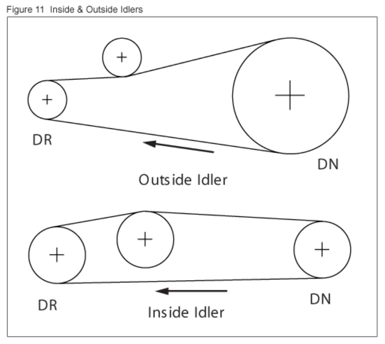
RECOMMENDED USE OF IDLERS
The use of idlers should be restricted to those cases in which they are functionally necessary. The usual cases are:
(a) As a means of applying tension when centers are not adjustable.
(b) To increase the number of teeth in mesh on the small pulley of relatively high ratio drives. Idlers should be located on the slack side of the belt. For inside idlers, grooved pulleys are recommended up to 40 grooves. On larger diameters, flat, uncrowned pulleys may be used. Outside idlers should be flat, uncrowned pulleys. Idler diameters should not be smaller than the smallest pulley diameter in the system and idler arc of contact should be held to a minimum. Fixed idlers are recommended.
| BELT SELECTION | BELT WIDTH (INCHES) | ||||||
|---|---|---|---|---|---|---|---|
| 0.12 | 0.19 | 0.25 | 0.38 | 0.50 | 0.75 | 1.00 | |
| MXL (0.080) | 0.43 | 0.73 | 1.00 | ||||
| XL (0.200) | 0.62 | 1.00 | |||||
| L (0.375) | 0.45 | 0.72 | 1.00 | ||||
| RPM OF FASTER SHAFT | BELT SECTION AND PITCH, INCHES | ||
|---|---|---|---|
| MXL (0.080) | XL (0.200) | L (0.375) | |
| 3450 | 16 | 12 | 16 |
| 1750 | 14 | 12 | 14 |
| 1160 | 12 | 10 | 12 |
| 870 | - | 10 | 12 |
Note: No increase in belt width will correct the adverse effects of using sub-minimum pulleys.
0.0870.0930.0990.1020000.140.160.190.210.230.260.280.320.35
| RPM of Faster Shaft | RATED HORSEPOWER FOR SMALL PULLEY (NUMBER OF GROOVES AND PITCH DIAMETER) | |||||||||
|---|---|---|---|---|---|---|---|---|---|---|
| 10XL | 12XL | 14XL | 16XL | 18XL | 20XL | 22XL | 24XL | 28XL | 30XL | |
| 0.637 | 0.764 | 0.891 | 1.019 | 1.146 | 1.273 | 1.401 | 1.528 | 1.783 | 1.910 | |
| 950 | 0.055 | 0.066 | 0.077 | 0.089 | 0.10 | 0.11 | 0.12 | 0.13 | 0.15 | 0.17 |
| 1160 | 0.068 | 0.081 | 0.095 | 0.11 | 0.12 | 0.14 | 0.15 | 0.16 | 0.19 | 0.20 |
| 1425 | 0.083 | 0.10 | 0.12 | 0.13 | 0.15 | 0.17 | 0.18 | 0.20 | 0.23 | 0.25 |
| 1750 | 0.10 | 0.12 | 0.14 | 0.16 | 0.18 | 0.20 | 0.22 | 0.24 | 0.28 | 0.30 |
| 2850 | 0.17 | 0.20 | 0.23 | 0.26 | 0.30 | 0.33 | 0.36 | 0.39 | 0.46 | 0.49 |
| 3450 | 0.20 | 0.24 | 0.28 | 0.32 | 0.36 | 0.40 | 0.43 | 0.47 | 0.55 | 0.58 |
| 100 | 0.006 | 0.007 | 0.008 | 0.009 | 0.010 | 0.012 | 0.013 | 0.014 | 0.016 | 0.017 |
| 200 | 0.012 | 0.014 | 0.016 | 0.019 | 0.021 | 0.023 | 0.026 | 0.028 | 0.033 | 0.035 |
| 300 | 0.018 | 0.021 | 0.024 | 0.028 | 0.031 | 0.035 | 0.038 | 0.042 | 0.049 | 0.052 |
| 400 | 0.023 | 0.028 | 0.033 | 0.037 | 0.042 | 0.047 | 0.051 | 0.056 | 0.065 | 0.070 |
| 500 | 0.029 | 0.035 | 0.041 | 0.047 | 0.052 | 0.058 | 0.064 | 0.070 | 0.082 | 0.087 |
| 600 | 0.035 | 0.042 | 0.049 | 0.056 | 0.063 | 0.070 | 0.077 | 0.084 | 0.098 | 0.10 |
| 700 | 0.041 | 0.049 | 0.057 | 0.065 | 0.073 | 0.082 | 0.090 | 0.098 | 0.11 | 0.12 |
| 800 | 0.047 | 0.056 | 0.065 | 0.075 | 0.084 | 0.093 | 0.10 | 0.11 | 0.13 | 0.14 |
| 900 | 0.053 | 0.063 | 0.073 | 0.084 | 0.094 | 0.10 | 0.12 | 0.13 | 0.15 | 0.16 |
| 1000 | 0.058 | 0.070 | 0.082 | 0.093 | 0.10 | 0.12 | 0.13 | 0.14 | 0.16 | 0.17 |
| 1100 | 0.064 | 0.077 | 0.090 | 0.10 | 0.12 | 0.13 | 0.14 | 0.15 | 0.18 | 0.19 |
| 1200 | 0.070 | 0.084 | 0.098 | 0.11 | 0.13 | 0.14 | 0.15 | 0.17 | 0.20 | 0.21 |
| 1300 | 0.076 | 0.091 | 0.11 | 0.12 | 0.14 | 0.05 | 0.17 | 0.18 | 0.21 | 0.23 |
| 1400 | 0.082 | 0.098 | 0.11 | 0.13 | 0.15 | 0.16 | 0.18 | 0.20 | 0.23 | 0.24 |
| 1500 | 0.070 | 0.10 | 0.12 | 0.14 | 0.16 | 0.17 | 0.19 | 0.21 | 0.24 | 0.26 |
| 1600 | 0.070 | 0.11 | 0.13 | 0.15 | 0.17 | 0.19 | 0.20 | 0.22 | 0.26 | 0.28 |
| 1700 | 0.070 | 0.12 | 0.14 | 0.16 | 0.18 | 0.20 | 0.22 | 0.24 | 0.28 | 0.30 |
| 1800 | 0.070 | 0.13 | 0.15 | 0.17 | 0.19 | 0.21 | 0.23 | 0.25 | 0.29 | 0.31 |
| 0.11 | 0.12 | 0.11 | 0.11 | 0.11 | 0.11 | 0.11 | 0.11 | 0.11 | 0.11 | 0.11 |
| 2200 | 0.13 | 0.15 | 0.18 | 0.20 | 0.23 | 0.25 | 0.28 | 0.31 | 0.36 | 0.38 |
| 2400 | 0.14 | 0.17 | 0.20 | 0.22 | 0.25 | 0.28 | 0.31 | 0.33 | 0.39 | 0.41 |
| 2600 | 0.15 | 0.18 | 0.21 | 0.24 | 0.27 | 0.30 | 0.33 | 0.36 | 0.42 | 0.45 |
| 2800 | 0.16 | 0.20 | 0.23 | 0.26 | 0.29 | 0.32 | 0.36 | 0.39 | 0.45 | 0.48 |
| 3000 | 0.17 | 0.21 | 0.24 | 0.28 | 0.31 | 0.35 | 0.38 | 0.41 | 0.48 | 0.51 |
| 3200 | 0.19 | 0.22 | 0.26 | 0.30 | 0.33 | 0.37 | 0.40 | 0.44 | 0.51 | 0.54 |
| 3400 | 0.20 | 0.24 | 0.28 | 0.31 | 0.35 | 0.39 | 0.43 | 0.47 | 0.54 | 0.58 |
| 3600 | 0.21 | 0.25 | 0.29 | 0.33 | 0.37 | 0.41 | 0.45 | 0.49 | 1.57 | 0.61 |
| 3800 | 0.22 | 0.26 | 0.31 | 0.35 | 0.39 | 0.44 | 0.48 | 0.52 | 0.60 | 0.64 |
| 4000 | 0.23 | 0.28 | 0.32 | 0.37 | 0.41 | 0.46 | 0.50 | 0.54 | 0.63 | 0.67 |
| 4200 | 0.24 | 0.29 | 0.34 | 0.39 | 0.43 | 0.48 | 0.52 | 0.57 | 0.66 | 0.70 |
| 4400 | 0.26 | 0.31 | 0.35 | 0.40 | 0.45 | 0.50 | 0.55 | 0.59 | 0.68 | 0.73 |
| 4600 | 0.27 | 0.32 | 0.37 | 0.42 | 0.47 | 0.52 | 0.57 | 0.62 | 0.71 | 0.76 |
| 4800 | 0.28 | 0.33 | 0.39 | 0.44 | 0.49 | 0.54 | 0.59 | 0.64 | 0.74 | 0.79 |
| 5000 | 0.29 | 0.35 | 0.40 | 0.46 | 0.51 | 0.56 | 0.62 | 0.67 | 0.77 | 0.81 |
| 5500 | 0.50 | 0.56 | 0.62 | 0.67 | 0.73 | 0.83 | 0.88 | |||
| 6000 | 0.54 | 0.61 | 0.67 | 0.73 | 0.79 | 0.89 | 0.94 | |||
| 6500 | 0.59 | 0.65 | 0.72 | 0.78 | 0.84 | 0.95 | 1.00 | |||
| 7000 | 0.63 | 0.70 | 0.77 | 0.83 | 0.89 | 1.01 | 1.06 | |||
| 7500 | 0.67 | 0.74 | 0.81 | 0.88 | 0.94 | 1.06 | 1.10 | |||
| 8000 | 0.79 | 0.86 | 0.93 | 0.99 | 1.10 | 1.15 | ||||
| 8500 | 0.83 | 0.90 | 0.97 | 1.03 | 1.14 | 1.18 | ||||
| 9000 | 0.87 | 0.94 | 1.01 | 1.08 | 1.18 | 1.22 | ||||
| 9500 | 0.91 | 0.98 | 1.05 | 1.11 | 1.21 | 1.24 | ||||
| 10000 | 0.94 | 1.02 | 1.09 | 1.15 | 1.23 | 1.26 | ||||
| RPM of Faster Shaft | RATED HORSEPOWER FOR SMALL PULLEY (NUMBER OF GROOVES AND PITCH DIAMETER) | ||||||||||||||||||
|---|---|---|---|---|---|---|---|---|---|---|---|---|---|---|---|---|---|---|---|
| 10L | 12L | 14L | 15L | 18L | 20L | 22L | 24L | 26L | 28L | 30L | 32L | 36L | 40L | 44L | 48L | ||||
| 1.194 | 1.432 | 1.671 | 1.910 | 2.149 | 2.387 | 2.628 | 2.865 | 3.104 | 3.342 | 3.581 | 3.820 | 4.297 | 4.775 | 5.252 | 5.730 | ||||
| 725 | 0.38 | 0.45 | 0.53 | 0.60 | 0.68 | 0.75 | 0.83 | 0.90 | 0.98 | 1.05 | 1.13 | 1.20 | 1.35 | 1.50 | 1.64 | 1.79 | |||
| 870 | 0.45 | 0.54 | 0.63 | 0.72 | 0.81 | 0.90 | 0.99 | 1.08 | 1.17 | 1.26 | 1.35 | 1.44 | 1.61 | 1.79 | 1.96 | 2.14 | |||
| 950 | 0.49 | 0.59 | 0.69 | 0.79 | 0.89 | 0.99 | 1.08 | 1.18 | 1.28 | 1.37 | 1.47 | 1.57 | 1.76 | 1.95 | 2.14 | 2.32 | |||
| 1160 | 0.60 | 0.72 | 0.84 | 0.96 | 1.08 | 1.20 | 1.32 | 1.44 | 1.56 | 1.67 | 1.79 | 1.91 | 2.14 | 2.36 | 2.59 | 2.81 | |||
| 1425 | 0.74 | 0.89 | 1.03 | 1.18 | 1.33 | 1.47 | 1.62 | 1.76 | 1.90 | 2.04 | 2.18 | 2.32 | 2.60 | 2.87 | 3.14 | 3.40 | |||
| 1750 | 0.91 | 1.09 | 1.27 | 1.45 | 1.62 | 1.80 | 1.97 | 2.15 | 2.32 | 2.49 | 2.66 | 2.82 | 3.15 | 3.47 | 3.77 | 4.07 | |||
| 2850 | 1.76 | 2.04 | 2.32 | 2.60 | 2.87 | 3.14 | 3.40 | 3.65 | 3.89 | 4.13 | 4.36 | 4.79 | 5.17 | 5.52 | 5.81 | ||||
| 3450 | 2.46 | 2.79 | 3.11 | 3.42 | 3.73 | 4.02 | 4.30 | 4.57 | 4.82 | 5.06 | 5.48 | 5.84 | 6.11 | 6.29 | |||||
| 100 | 0.05 | 0.06 | 0.07 | 0.08 | 0.09 | 0.10 | 0.11 | 0.12 | 0.14 | 0.15 | 0.16 | 0.17 | 0.19 | 0.21 | 0.23 | 0.25 | |||
| 200 | 0.10 | 0.12 | 0.15 | 0.17 | 0.19 | 0.21 | 0.23 | 0.25 | 0.27 | 0.29 | 0.31 | 0.33 | 0.37 | 0.42 | 0.46 | 0.50 | |||
| 300 | 0.16 | 0.19 | 0.22 | 0.25 | 0.28 | 0.31 | 0.34 | 0.37 | 0.41 | 0.44 | 0.47 | 0.50 | 0.56 | 0.62 | 0.69 | 0.75 | |||
| 400 | 0.21 | 0.25 | 0.29 | 0.33 | 0.37 | 0.42 | 0.46 | 0.50 | 0.54 | 0.58 | 0.62 | 0.67 | 0.75 | 0.83 | 0.91 | 1.00 | |||
| 500 | 0.26 | 0.31 | 0.36 | 0.42 | 0.47 | 0.52 | 0.57 | 0.62 | 0.68 | 0.73 | 0.78 | 0.83 | 0.93 | 1.04 | 1.14 | 1.24 | |||
| 600 | 0.31 | 0.37 | 0.44 | 0.50 | 0.56 | 0.62 | 0.69 | 0.75 | 0.81 | 0.87 | 0.93 | 1.00 | 1.12 | 1.24 | 1.36 | 1.49 | |||
| 700 | 0.36 | 0.44 | 0.51 | 0.58 | 0.65 | 0.73 | 0.80 | 0.87 | 0.94 | 1.02 | 1.09 | 1.16 | 1.30 | 1.45 | 1.59 | 1.73 | |||
| 800 | 0.42 | 0.50 | 0.58 | 0.67 | 0.75 | 0.83 | 0.91 | 1.00 | 1.08 | 1.16 | 1.24 | 1.32 | 1.49 | 1.65 | 1.81 | 1.97 | |||
| 900 | 0.47 | 0.56 | 0.65 | 0.75 | 0.84 | 0.93 | 1.03 | 1.12 | 1.21 | 1.30 | 1.40 | 1.49 | 1.67 | 1.85 | 2.03 | 2.21 | |||
| 1000 | 0.52 | 0.62 | 0.73 | 0.83 | 0.93 | 1.04 | 1.14 | 1.24 | 1.34 | 1.45 | 1.55 | 1.65 | 1.85 | 2.05 | 2.25 | 2.44 | |||
| 1100 | 0.57 | 0.69 | 0.80 | 0.91 | 1.03 | 1.14 | 1.25 | 1.36 | 1.48 | 1.59 | 1.70 | 1.81 | 2.03 | 2.25 | 2.46 | 2.67 | |||
| 1200 | 0.62 | 0.75 | 0.87 | 1.00 | 1.12 | 1.24 | 1.36 | 1.49 | 1.61 | 1.73 | 1.85 | 1.97 | 2.21 | 2.44 | 2.67 | 2.90 | |||
| 1300 | 0.63 | 0.81 | 0.94 | 1.08 | 1.21 | 1.34 | 1.48 | 1.61 | 1.74 | 1.87 | 2.00 | 2.13 | 2.38 | 2.63 | 2.88 | 3.12 | |||
| 1400 | 0.73 | 0.87 | 1.02 | 1.16 | 1.30 | 1.45 | 1.59 | 1.73 | 1.87 | 2.01 | 2.15 | 2.29 | 2.56 | 2.82 | 3.09 | 3.34 | |||
| 1500 | 0.78 | 0.93 | 1.09 | 1.24 | 1.40 | 1.55 | 1.70 | 1.85 | 2.00 | 2.15 | 2.30 | 2.44 | 2.73 | 3.01 | 3.29 | 3.56 | |||
| 1600 | 0.83 | 1.00 | 1.16 | 1.32 | 1.49 | 1.65 | 1.81 | 1.97 | 2.13 | 2.29 | 2.44 | 2.60 | 2.90 | 3.20 | 3.49 | 3.77 | |||
| 1700 | 0.88 | 1.06 | 1.23 | 1.41 | 1.58 | 1.75 | 1.92 | 2.09 | 2.26 | 2.42 | 2.59 | 2.75 | 3.07 | 3.38 | 3.68 | 3.97 | |||
| 1800 | 1.12 | 1.30 | 1.49 | 1.67 | 1.85 | 2.03 | 2.21 | 2.38 | 2.56 | 2.73 | 2.90 | 3.23 | 3.56 | 3.87 | 4.17 | ||||
| 1900 | 1.18 | 1.37 | 1.57 | 1.76 | 1.95 | 2.14 | 2.32 | 2.51 | 2.69 | 2.87 | 3.05 | 3.40 | 3.73 | 4.05 | 4.36 | ||||
| 2000 | 1.24 | 1.45 | 1.65 | 1.85 | 2.05 | 2.25 | 2.44 | 2.63 | 2.82 | 3.01 | 3.20 | 3.56 | 3.90 | 4.23 | 4.54 | ||||
| 2200 | 1.36 | 1.59 | 1.81 | 2.03 | 2.25 | 2.46 | 2.67 | 2.88 | 3.09 | 3.29 | 3.49 | 3.87 | 4.23 | 4.57 | 4.89 | ||||
| 2400 | 1.49 | 1.73 | 1.97 | 2.21 | 2.44 | 2.67 | 2.90 | 3.12 | 3.34 | 3.56 | 3.77 | 4.17 | 4.54 | 4.89 | 5.21 | ||||
| 2600 | 1.61 | 1.87 | 2.13 | 2.38 | 2.63 | 2.88 | 3.12 | 3.36 | 3.59 | 3.82 | 4.04 | 4.45 | 4.84 | 5.19 | 5.50 | ||||
| 2800 | 1.73 | 2.01 | 2.29 | 2.56 | 2.82 | 3.09 | 3.34 | 3.59 | 3.83 | 4.07 | 4.30 | 4.72 | 5.11 | 5.45 | 5.75 | ||||
| 3000 | 1.85 | 2.15 | 2.44 | 2.73 | 3.01 | 3.29 | 3.56 | 3.82 | 4.07 | 4.31 | 4.54 | 4.98 | 5.36 | 5.69 | 5.97 | ||||
| 3200 | 2.29 | 2.60 | 2.90 | 3.20 | 3.49 | 3.77 | 4.04 | 4.29 | 4.54 | 4.78 | 5.21 | 5.59 | 5.90 | 6.14 | |||||
| 3400 | 2.42 | 2.75 | 3.07 | 3.38 | 3.68 | 3.97 | 4.25 | 4.51 | 4.77 | 5.00 | 5.43 | 5.79 | 6.07 | 6.27 | |||||
| 3600 | 2.56 | 2.90 | 3.23 | 3.56 | 3.87 | 4.17 | 4.45 | 4.72 | 4.98 | 5.21 | 5.63 | 5.97 | 6.21 | 6.35 | |||||
| 3800 | 2.69 | 3.05 | 3.40 | 3.73 | 4.05 | 4.36 | 4.65 | 4.92 | 5.17 | 5.41 | 5.81 | 6.11 | 6.31 | 6.39 | |||||
| 4000 | 2.82 | 3.20 | 3.56 | 3.90 | 4.23 | 4.54 | 4.84 | 5.11 | 5.36 | 5.59 | 5.97 | 6.23 | 5.96.37 | 6.37 | |||||
| 4200 | 3.34 | 3.71 | 4.07 | 4.40 | 4.72 | 5.02 | 5.29 | 5.53 | 5.75 | 6.10 | 6.32 | 6.39 | 6.30 | ||||||
| 4400 | 3.49 | 3.87 | 4.23 | 4.57 | 4.89 | 5.19 | 5.45 | 5.69 | 5.90 | 6.21 | 6.37 | 6.36 | #6.17 | ||||||
| 4600 | 3.63 | 4.02 | 4.39 | 4.74 | 5.06 | 5.35 | 5.61 | 5.84 | 6.03 | 6.29 | 6.39 | 6.29 | #5.98 | ||||||
| 4800 | 3.77 | 4.17 | 4.54 | 4.89 | 5.21 | 5.50 | 5.75 | 5.97 | 6.14 | 6.35 | 6.37 | #6.17 | #5.73 | ||||||
| 5000 | 3.90 | 4.31 | 4.69 | 5.04 | 5.36 | 5.64 | 5.88 | 6.09 | 6.23 | 6.38 | 6.31 | #6.00 | #5.41 | ||||||
| 5200 | 4.04 | 4.43 | 4.84 | 5.19 | 5.50 | 5.77 | 6.00 | 6.18 | 6.30 | 6.38 | 6.22 | #5.78 | #5.03 | ||||||
| 5400 | 4.17 | 4.59 | 4.98 | 5.32 | 5.63 | 5.89 | 6.10 | 6.25 | 6.35 | 6.36 | 6.36 | #5.50 | #4.57 | ||||||
| 5600 | 4.30 | 4.72 | 5.11 | 5.45 | 5.75 | 6.00 | 6.19 | 6.32 | 6.38 | 6.30 | #3.90 | #5.17 | #4.05 | ||||||
| 5800 | 4.42 | 4.85 | 5.24 | 5.58 | 5.86 | 6.09 | 6.26 | 6.36 | 6.39 | 6.21 | #5.68 | #4.77 | #3.44 | ||||||
| 6000 | 4.54 | 4.98 | 5.36 | 5.69 | 5.97 | 6.18 | 6.32 | 6.38 | 6.37 | #6.08 | #5.41 | #4.32 | #2.76 | ||||||