


Synchronous Belts
SIZE DESIGNATIONS
Synchronous Belt sizes are identified by a standard number. The first digits specify the belt length to one-tenth inch followed by the belt section (pitch) designation. The digits following the belt section designation represent the nominal belt width times 100. For example, an L section belt 30.000 inches in pitch length and 0.75 inches in width would be specified as a 300L075 Synchronous Belt. The nomenclature for double-sided belts will be the same as for single-sided belts with the addition of the prefix “D” in front of the belt section – Example 300DL075.
STANDARD SECTIONS
Belt sections are specified in terms of “pitch”. Table 8 gives the Standard Belt Sections and their corresponding “pitch”.
NOMINAL TOOTH DIMENSIONS
Table 9 and Figure 7 show the nominal tooth dimensions for each of the standard belt sections. The tooth dimensions for double-sided belts are identical to those of a single-sided belt.
PITCH LENGTHS
Standard belt pitch lengths, belt length designations and numbers of teeth are shown in Table 10.
WIDTHS
Standard belt widths and width designations are shown in Table 11.
| BELT SELECTION | PITCH | hg | hd |
|---|---|---|---|
| MXL | 0.080 | 0.045 | |
| XL | 0.200 | 0.090 | |
| L | 0.375 | 0.14 | |
| DXL | 0.200 | 0.120 | 0.120 |
| DL | 0.375 | 0.180 | 0.180 |
| BELT SELECTION | SS TOOTH ANGLE (DEGREES) | ht | bt | ra | rr |
|---|---|---|---|---|---|
| MXL (0.080) | 40 | 0.020 | 0.045 | 0.005 | 0.005 |
| XL (0.200) | 50 | 0.050 | 0.101 | 0.015 | 0.015 |
| L (0.375) | 40 | 0.075 | 0.183 | 0.020 | 0.020 |
| DXL (0.200) | 40 | 0.050 | 0.101 | 0.015 | 0.015 |
| DL (0.375) | 40 | 0.075 | 0.183 | 0.020 | 0.020 |
| BELT LENGTH DESIGNATION | PITCH LENGTH | PERMISSIBLE DEVIATION FROM STANDARD LENGTH | NUMBER OF TEETH FOR STANDARD LENGTHS | ||
|---|---|---|---|---|---|
| MXL (0.080) | XL (0.200) | L (0.375) | |||
| 36 | 3.600 | ±0.016 | 45 | ||
| 40 | 4.000 | ±0.016 | 50 | ||
| 44 | 4.400 | ±0.016 | 55 | ||
| 48 | 4.800 | ±0.016 | 60 | ||
| 56 | 5.600 | ±0.016 | 70 | ||
| 60 | 6.000 | ±0.016 | 75 | 30 | |
| 64 | 6.400 | ±0.016 | 80 | ||
| 70 | 7.000 | ±0.016 | 35 | ||
| 72 | 7.200 | ±0.016 | 90 | ||
| 80 | 8.000 | ±0.016 | 100 | 40 | |
| 88 | 8.800 | ±0.016 | 110 | ||
| 90 | 9.000 | ±0.016 | 45 | ||
| 100 | 10.000 | ±0.016 | 125 | 50 | |
| 110 | 11.018 | ±0.018 | 55 | ||
| 112 | 11.200 | ±0.018 | 140 | ||
| 120 | 12.000 | ±0.018 | 60 | ||
| 124 | 12.375 | ±0.018 | 33 | ||
| 124 | 12.400 | ±0.018 | 155 | ||
| 130 | 13.000 | ±0.018 | 65 | ||
| 140 | 14.000 | ±0.018 | 175 | 70 | |
| 150 | 15.000 | ±0.018 | 75 | 40 | |
| 160 | 16.000 | ±0.020 | 200 | 80 | |
| 170 | 17.000 | ±0.020 | 85 | ||
| 180 | 18.000 | ±0.020 | 225 | 90 | |
| 187 | 18.750 | ±0.020 | 50 | ||
| 190 | 19.000 | ±0.020 | 95 | ||
| 200 | 20.000 | ±0.020 | 250 | 100 | |
| 210 | 21.000 | ±0.024 | 105 | 56 | |
| 220 | 22.000 | ±0.024 | 110 | ||
| 225 | 22.500 | ±0.024 | 60 | ||
| 230 | 23.000 | ±0.024 | 115 | ||
| 240 | 24.000 | ±0.024 | 120 | 64 | |
| 250 | 25.000 | ±0.024 | 125 | ||
| 255 | 25.500 | ±0.024 | 68 | ||
| 260 | 26.000 | ±0.024 | 130 | ||
| 270 | 27.000 | ±0.024 | 72 | ||
| 285 | 28.500 | ±0.024 | 76 | ||
| 300 | 30.000 | ±0.024 | 80 | ||
| 322 | 32.250 | ±0.026 | 86 | ||
| 330 | 33.000 | ±0.026 | |||
| BELT LENGTH DESIGNATION | PITCH LENGTH | PERMISSIBLE DEVIATION FROM STANDARD LENGTH | NUMBER OF TEETH FOR STANDARD LENGTHS | ||
|---|---|---|---|---|---|
| MXL (0.080) | XL (0.200) | L (0.375) | |||
| 345 | 34.500 | ±0.026 | 92 | ||
| 360 | 36.000 | ±0.026 | |||
| 367 | 36.750 | ±0.026 | 98 | ||
| 390 | 39.000 | ±0.026 | 104 | ||
| 420 | 42.000 | ±0.030 | 112 | ||
| 450 | 45.000 | ±0.030 | 120 | ||
| 480 | 48.000 | ±0.030 | 128 | ||
| 507 | 50.750 | ±0.032 | |||
| 510 | 51.000 | ±0.032 | 136 | ||
| 540 | 54.000 | ±0.032 | 144 | ||
| 560 | 56.000 | ±0.032 | |||
| 570 | 57.000 | ±0.032 | 160 | ||
| 600 | 60.000 | ±0.032 | |||
| 630 | 63.000 | ±0.034 | |||
| 660 | 66.000 | ±0.034 | |||
| 700 | 70.000 | ±0.034 | |||
| 750 | 75.000 | ±0.036 | |||
| 770 | 77.000 | ±0.036 | |||
| 800 | 80.000 | ±0.036 | |||
| 840 | 84.000 | ±0.038 | |||
| 850 | 85.000 | ±0.038 | |||
| 900 | 90.000 | ±0.038 | |||
| 980 | 98.000 | ±0.040 | |||
| 1000 | 100.000 | ±0.040 | |||
| 1100 | 110.000 | ±0.042 | |||
| 1120 | 112.000 | ±0.044 | |||
| 1200 | 120.000 | ±0.044 | |||
| 1250 | 125.000 | ±0.046 | |||
| 1260 | 126.000 | ±0.046 | |||
| 1400 | 140.000 | ±0.048 | |||
| 1540 | 154.000 | ±0.052 | |||
| 1600 | 160.000 | ±0.052 | |||
| 1700 | 170.000 | ±0.054 | |||
| 1750 | 175.000 | ±0.056 | |||
| 1800 | 180.000 | ±0.056 | |||
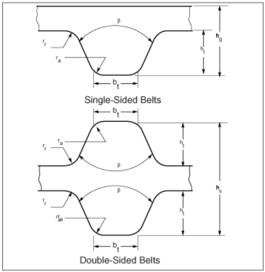
Figure 7 Tooth Dimensions
LENGTH TOLERANCES
The belt length tolerances shown in Table 10 apply to all belt sections and represent the total manufacturing tolerance on the belt length. For fixed center drives consult the belt manufacturer.
WIDTH TOLERANCE
Belt width tolerances for all belt sections are given in Table 11.
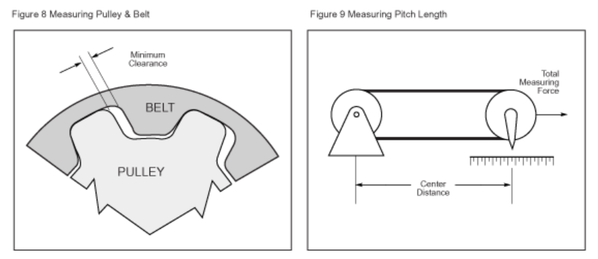
LENGTH DETERMINATION
The pitch length of a belt shall be determined by placing the belt on a measuring fixture comprising two pulleys of equal diameter, a method of applying force and a means of measuring the center distance between the two pulleys.
One of the two pulleys is fixed in position while the other is movable along a graduated scale. Recommended measuring pulley dimensions are shown in Table 12.
The fixture is shown schematically in Figure 9. Any pair of equal diameter pulleys of the proper pitch and manufactured to the specifications shown in the “Synchronous Belt Pulleys” section may be used for measuring provided the clearance between the theoretical belt tooth width and the groove width of the measuring pulley is not less than the minimum values shown in Table 12. Measuring forces for the standard belt sections and widths are shown in Table 13.
In measuring the length of a belt, the belt should be rotated at least two revolutions of the belt in order to (a) seat the belt properly in the pulley grooves, (b) divide equally the total force between the two strands of the belt, and (c) determine the midpoint of the center distance travel of the movable pulley which shall define the center distance. The pitch length shall be calculated by adding the pitch circumference of one of the measuring pulleys to twice the measured center distance between the two pulleys.
| BELT SELECTION | STANDARD BELT WIDTHS | TOLERANCES ON WIDTH FOR BELT PITCH LENGTHS | |||
|---|---|---|---|---|---|
| DESIGNATION | DIMENSIONS | UP TO AND INCLUDING 33 INCHES | OVER 33 INCHES UP TO AND INCLUDING 66 INCHES | OVER 66 INCHES | |
| MXL (0.080) | 012 | 0.12 | +0.02 | - | - |
| MXL (0.080) | 019 | 0.19 | -0.03 | ||
| MXL (0.080) | 025 | 0.25 | |||
| XL (0.200) | 025 | 0.25 | +0.02 | - | - |
| XL (0.200) | -0.03 | ||||
| XL (0.200) | 037 | 0.38 | |||
| L (0.375) | 050 | 0.50 | +0.03 | +0.03 | - |
| L (0.375) | 075 | 0.75 | -0.03 | -0.05 | |
| L (0.375) | 100 | 1.00 | |||
| BELT SELECTION | NUMBER OF TEETH | PITCH CIRCUMFERENCE | OUTSIDE DIAMETER | RADIAL RUNOUT T.I.R.* | AXIAL RUNOUT T.I.R.* | MINIMUM CLEARANCE (SEE FIG. 8) |
|---|---|---|---|---|---|---|
| MXL (0.080) | 20 | 1.600 | 0.4893 ±0.0005 |
0.0005 | 0.001 | 0.010 |
| XL (0.200) | 10 | 2.000 | 0.6166 ±0.0005 |
0.0005 | 0.001 | 0.012 |
| L (0.375) | 16 | 6.000 | 1.8799 ±0.0005 |
0.0005 | 0.001 | 0.013 |
| BELT SELECTION | BELT WIDTH (INCHES) | |||||||||||
|---|---|---|---|---|---|---|---|---|---|---|---|---|
| 0.12 | 0.19 | 0.25 | 0.38 | 0.50 | 0.75 | 1.00 | 1.50 | 2.00 | 3.00 | 4.00 | 5.00 | |
| MXL (0.080) | 3 | 4.5 | 5 | |||||||||
| XL (0.200) | 8 | 12 | ||||||||||
| L (0.375) | 24 | 40 | 55 | |||||||||